El Instituto de Arquitectura de Japón (AIJ) ha presentado una serie de escenarios de referencia bien conocidos de la simulación de viento.
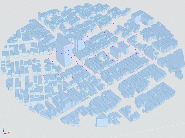
El siguiente artículo gira en torno al "Caso E - un complejo de edificios en una zona urbana real con una densa concentración de edificios de poca altura en la ciudad de Niigata".
A continuación, se simula el escenario descrito en RWIND2 y se comparan los resultados con los resultados simulados y experimentales del AIJ.
El Instituto de Arquitectura de Japón (AIJ) ha eine Reihe an bekannten Benchmark-Szenarien für Windsimulation vorgestellt.
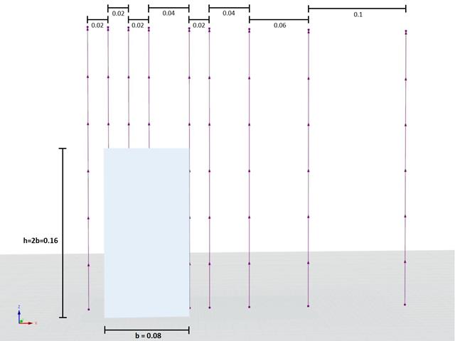
Der Nachfolgende Beitrag dreht sich dabei um den "Caso A - Edificio de gran altura con una forma 2: 1: 1".
Im Folgenden wird das beschriebene Szenario in RWIND2 nachgebildet und die Ergebnisse mit den simulierten und der experimentantellen Resultate des AIJ verglichen.
El Instituto de Arquitectura de Japón (AIJ) ha presentado una serie de escenarios de referencia bien conocidos de la simulación de viento.
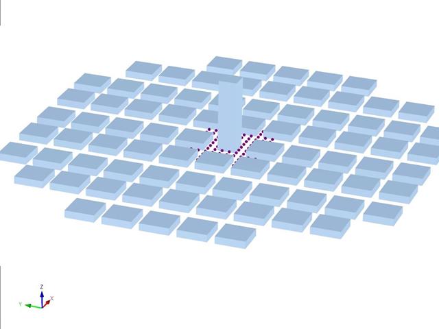
El siguiente artículo trata del "Caso D - Edificio de gran altura entre manzanas".
A continuación, se simula el escenario descrito en RWIND2 y se comparan los resultados con los resultados simulados y experimentales del AIJ.
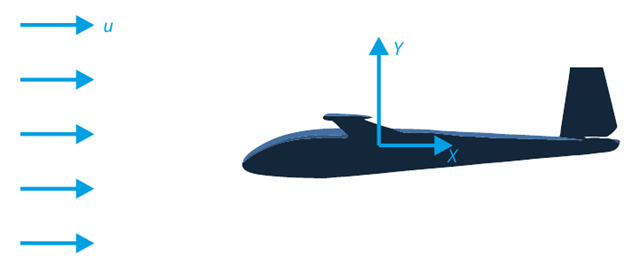
El objetivo de este ejemplo de verificación es analizar el flujo de fluidos alrededor de un planeador. La tarea consiste en determinar el coeficiente de arrastre y el coeficiente de sustentación con respecto al ángulo de incidencia. Estos coeficientes también se pueden dibujar en el gráfico de arrastre polar. El ángulo límite para el flujo de fluido laminar alrededor del perfil del ala también se puede determinar a partir del campo de velocidades. El modelo de CAD en 3D disponible (archivo STL) se utiliza en RWIND 2.
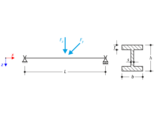
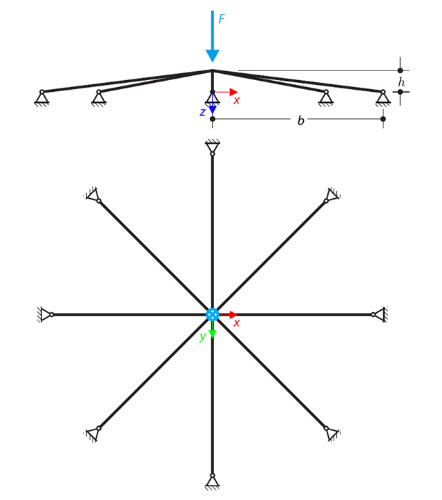
Una estructura hecha de un perfil en I está incrustada en los apoyos de la horquilla. The axial rotation is restricted on both ends while warping is enabled. The structure is loaded by two transverse forces in the middle. The verification example is based on the example introduced by Gensichen and Lumpe.
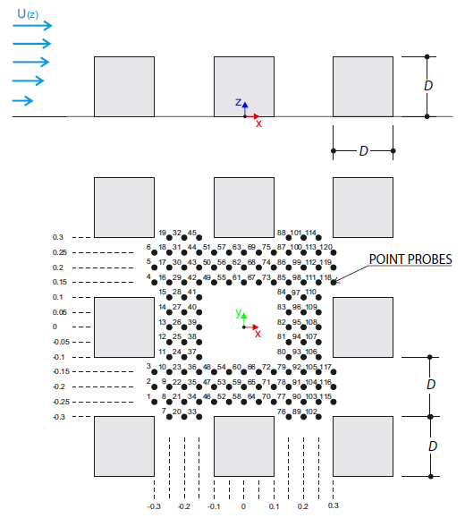
El ejemplo de verificación describe las cargas de viento en varias direcciones del viento en un modelo de un grupo de edificios. The model consists of eight cubes. The velocity fields obtained by the RWIND simulation are compared with the measured values from the experiment. The experimental data are measured using a thermistor anemometer in the wind tunnel.
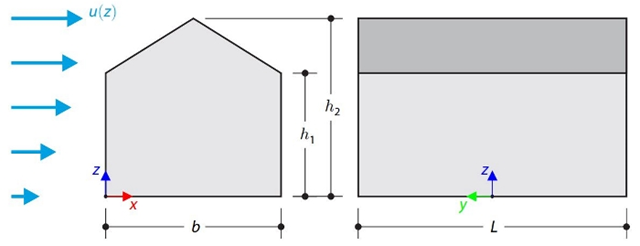
Este ejemplo de verificación compara los cálculos de la carga de viento en un edificio con cubierta a dos aguas utilizando la norma ASCE 7-16 y utilizando la simulación CFD en RWIND Simulation. The building is defined according to the sketch and the inflow velocity profile taken from the ASCE 7-16 standard.
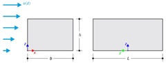
Este ejemplo de verificación compara los cálculos de la carga de viento en un edificio de cubierta plana utilizando la norma ASCE 7-16 y utilizando la simulación CFD en RWIND Simulation. The building is defined according to the sketch and the inflow velocity profile taken from the ASCE 7-16 standard.
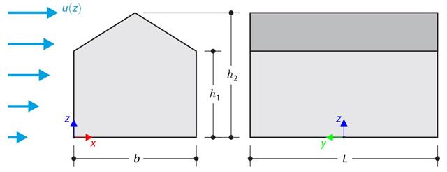
El ejemplo de verificación compara el cálculo de la carga de viento en un edificio con una cubierta a dos aguas utilizando la norma EN 1991-1-4 y utilizando la simulación CFD en RWIND Simulation. The building is defined according to the sketch, and the inflow velocity profile is taken according to the standard EN 1991-1-4.
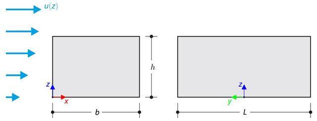
El ejemplo de verificación compara el cálculo de la carga de viento en un edificio con una cubierta plana utilizando la norma EN 1991-1-4 y utilizando la simulación CFD en RWIND Simulation. The building is defined according to the sketch, and the inflow velocity profile is taken according to the standard EN 1991-1-4.
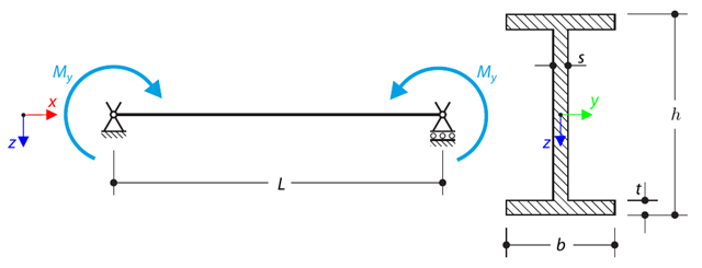
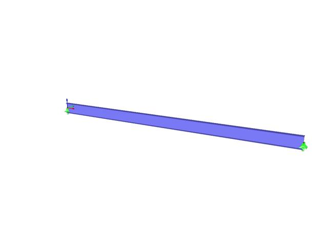
Una viga simplemente apoyada está cargada por flexión pura. Determine the critical load and corresponding load factor due to lateral buckling.
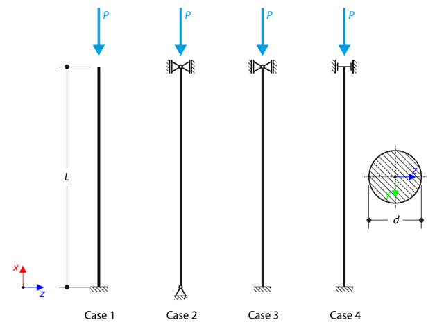
Una biela con una sección circular se apoya según cuatro casos básicos de pandeo de Euler y se somete a una fuerza de presión. Determine the critical load.
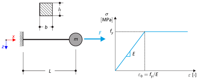
Este ejemplo de verificación se basa en el ejemplo de verificación 0122. A single-mass system without damping is subjected to an axial loading force. An ideal elastic-plastic material with characteristics is assumed. Determine the time course of the end-point deflection, velocity, and acceleration.
Una estructura superficial simétrica se compone de ocho barras de celosía iguales, que están incrustadas en los apoyos de las articulaciones. The structure is loaded by a concentrated force and alternatively by imposed nodal deformation over the critical limit point when the snap-through occurs. Imposed nodal deformation is used in RFEM 5 and RSTAB 8 to obtain the full equilibrium path of the snap-through. The self-weight is neglected in this example. Determine the relationship between the actual loading force and the deflection, considering large deformation analysis. Evaluate the load factor at the given deflections.
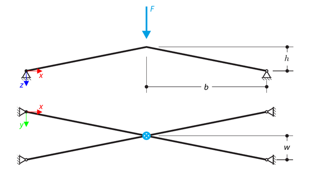
Una estructura se compone de cuatro barras de celosía, que están incrustadas en apoyos de articulación. The structure is loaded by a concentrated force and alternatively by imposed nodal deformation over the critical limit point, when snap-through occurs. Imposed nodal deformation is used in RFEM 5 and RSTAB 8 to obtain the full equilibrium path of the snap-through. The self-weight is neglected in this example. Determine the relationship between the actual loading force and the deflection, considering large deformation analysis. Evaluate the load factor at given deflections.
Consider an ASTM A992 W 18×50 beam forspan and uniform dead and live loads as shown in Figure 1. La barra está limitada a un canto nominal máximo de 18 pulgadas. The live load deflection is limited to L/360. The beam is simply supported and continuously braced. Verify the available flexural strength of the selected beam, based on LRFD and ASD.
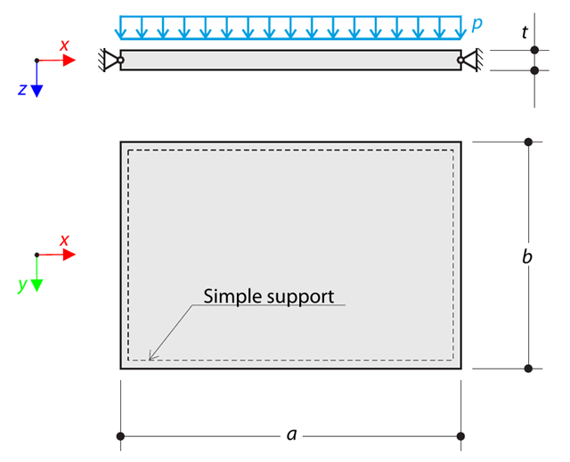
A thin rectangular orthotropic plate is simply supported and loaded by uniformly distributed pressure. The directions of axes x and y coincide with the principal directions. Determine la deformación máxima de la placa sin considerar el peso propio.
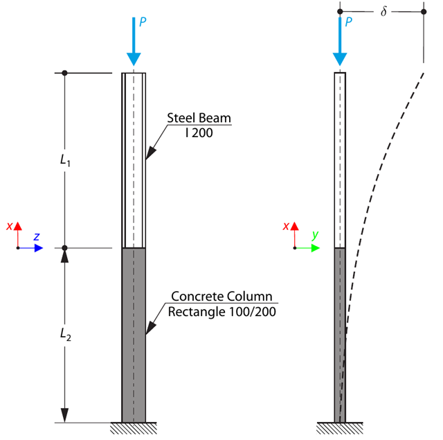
Un pilar se compone de una sección de hormigón (rectángulo 100/200) y una sección de acero (perfil I 200). It is subjected to pressure force. Determine the critical load and corresponding load factor. The theoretical solution is based on the buckling of a simple beam. In this case, two regions have to be taken into account due to different moments of inertia and material properties.
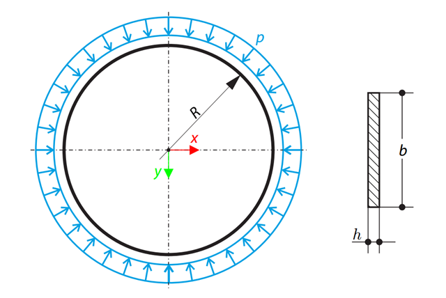
Un anillo circular delgado de sección rectangular está expuesto a una presión externa. Determine the critical load and corresponding load factor for in-plane buckling.
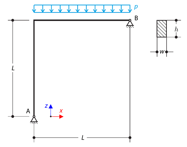
Una viga curva consta de dos vigas con una sección rectangular. The horizontal beam is loaded by distributed loading. While neglecting self-weight, determine the maximum stress on the top surface of the horizontal beam.
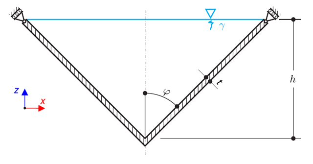
Un recipiente cónico de paredes delgadas está lleno de agua. Thus, it is loaded by hydrostatic pressure. While neglecting self-weight, determine the stresses in the surface line and circumferential direction. The analytical solution is based on the theory of thin-walled vessels. This theory was introduced in Verification Example 0084.
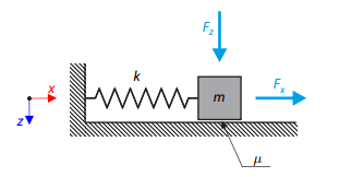
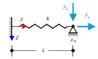
Un oscilador simple consta de una masa m (considerada solo en la dirección x) y un muelle lineal de rigidez k. The mass is embedded on a surface with Coulomb friction and is loaded by constant-in-time axial and transverse forces.
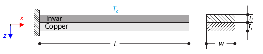
Una banda bimetálica se compone de invar y cobre. The left end of the bimetallic strip is fixed, and the right end is free, loaded by temperature difference. While neglecting self-weight, determine the deflection of the bimetallic strip (free end).
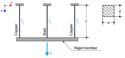
Una estructura de celosía consta de tres barras (una de acero y dos de cobre) unidas por una barra rígida. The structure is loaded by a concentrated force and a temperature difference. While neglecting self‑weight, determine the total deflection of the structure.
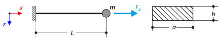
Un voladizo de sección rectangular tiene una masa al final. Furthermore, it is loaded by an axial force. Calculate the natural frequency of the structure. Neglect the self‑weight of the cantilever and consider the influence of the axial force for the stiffness modification.
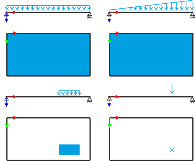
Una placa rectangular simplemente apoyada está sujeta a diferentes tipos de carga. Assuming only the small deformation theory and neglecting self-weight, determine the deflection at its centroid for each load type.
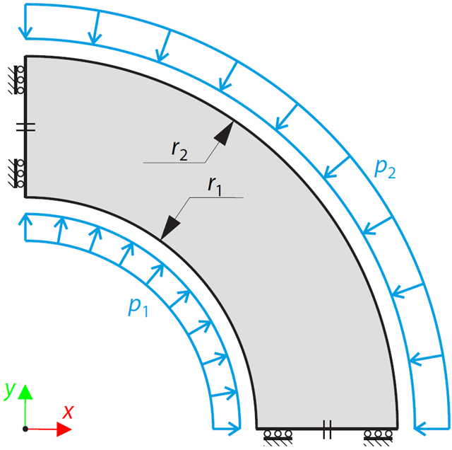
Este ejemplo es una modificación del ejemplo de verificación 0061; la única diferencia es que el material del recipiente es incompresible. An open‑ended, thick‑walled vessel is loaded by both inner and outer pressure. While neglecting self‑weight, the radial deflection of the inner and the outer radius is determined.
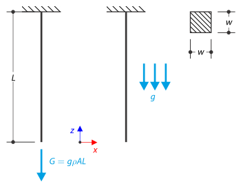
Una barra con una sección cuadrada está fijada en el extremo superior. The rod is loaded by self-weight. For comparison, the example is also modeled with the concentrated force load, the value of which is equal to the gravity. The aim of this verification example is to show the difference between these types of loading, although the total loading force is equal.
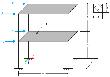
Este ejemplo sirve como demostración de la coacción del diafragma. The application is shown on a two-story structure. The structure is loaded by means of lateral forces according to Figure 1. Determine the maximum deflection of the structure ux in the direction of the loading forces using both the diaphragm constraint and the plate model of the floor.
El objetivo de este ejemplo es demostrar un proceso irreversible causado por la fricción. After the loading and unloading, the end-point is in a different position than where it was at the beginning. Determine the movement of the node in the X direction.